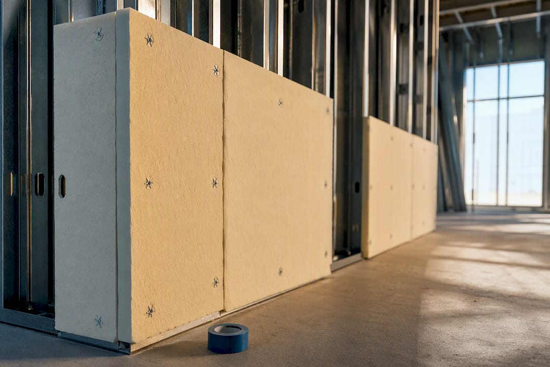
Yes, steel studs and structural steel create thermal bridges, and the effect is measurable, not theoretical: research shows wall assemblies commonly lose more heat than the insulation alone would suggest, typically between about 10% and 30%. The fix that moves the needle most is continuous exterior insulation, paired with engineered thermal breaks at structural penetrations. Start there before fussing over smaller details.
TL;DR:
- Continuous exterior insulation can reduce thermal bridging effects to below 1.5%, significantly improving wall performance.
- Repeating studs, tracks, fasteners, and structural penetrations are the main sources of heat loss in steel-framed walls, increasing overall U-values by up to 41%.
- Accurate estimation of thermal bridging requires specific psi and chi values, with complex geometry needing 3-D modeling for reliable results.
- Engineered load-bearing thermal breaks for structural connections are essential, with improper installation or compression negating their benefits.
- Proper specification, on-site thermal imaging, and early collaboration among architects, engineers, and builders are key to effectively managing thermal bridges.
Table of Contents
- What Is a Thermal Bridge in Steel Framing?
- How Much Heat Loss Does Thermal Bridging Actually Cause?
- Where Do Thermal Bridges Show Up in a Steel Frame?
- How Do You Calculate or Estimate Thermal Bridging?
- Which Mitigation Strategies Actually Work?
- What Should You Put in Your Spec and Site Checklist?
- Why Integrated Thermal-Bridge Control Pays Off
- Sources
What Is a Thermal Bridge in Steel Framing?
A thermal bridge is any spot in a wall assembly where heat finds an easier path through than the surrounding insulation allows. Steel is roughly 400 times more conductive than wood, which means every stud, track, and fastener in a steel frame acts like a tiny highway for heat, moving straight past the batt or board insulation stuffed between them.
Engineers sort these into three categories:
- Point bridges — a single screw, bolt, or fastener penetrating the insulation layer.
- Linear bridges — repeating studs, top and bottom tracks, or a continuous shelf angle running along a floor line.
- Planar bridges — a broad conductive surface, like an exposed structural steel beam spanning an entire wall face.
Linear bridges from repeating studs do the most damage in a typical steel-framed wall, simply because there are so many of them, spaced every 16 or 24 inches, each one quietly short-circuiting the insulation around it. The result on the interior surface is a cold spot, and cold spots are where condensation and eventual corrosion start.
How Much Heat Loss Does Thermal Bridging Actually Cause?
The numbers are bigger than most people expect. Across multiple parametric studies, stud-related U-value penalties commonly fall between 28% and 41%, meaning a wall rated for a certain insulation value performs a third worse in practice once you account for the steel running through it. Poorly detailed assemblies, where fasteners, tracks, and structural connections all compound, have shown far larger overestimates than that.
By the Numbers: Assembly-level heat loss from thermal bridging runs typically between about 10% and 30% higher than the insulation rating alone predicts, and builders can quantify the cumulative effect with a metric called the y-value: approximately 0.04 W/m²K represents a well-controlled building, about 0.08 is reasonable control, and roughly 0.12 is the default outcome when nobody addresses bridging at all.
That range matters because it is not a rounding error. Once vapor starts condensing on a cold stud flange behind drywall, corrosion and mold risk follow.
- Assembly heat loss increase: 10% to 30% typical
- Stud U-value penalty: 28% to 41% in most parametric studies
- y-value bands: 0.04 (low bridging) to 0.12 (no mitigation)
Where Do Thermal Bridges Show Up in a Steel Frame?
Knowing where to look on a set of drawings, or during a walkthrough, saves a lot of guesswork later. The usual suspects follow a predictable pattern:
- Stud bays and repeating studs — every 16 or 24 inches, each web and flange conducts heat straight through the cavity insulation.
- Top and bottom tracks — these run continuously along the floor and ceiling lines, creating a linear bridge that’s easy to miss on a section drawing.
- Fasteners and long through-screws — individually small, but numerous enough across a wall to add up as point bridges.
- Structural penetrations — shelf angles, exposed beams, and column lines that pass through the insulation layer without interruption.
- Envelope junctions — window and door reveals, parapets, and the transitions between wall types, where two different assemblies meet and details often get simplified.
Anywhere the drawings show steel touching both the interior and exterior faces of a wall without a break in between, assume you have a bridge until proven otherwise.
How Do You Calculate or Estimate Thermal Bridging?
Two Greek letters do most of the heavy lifting in this conversation: psi (ψ) for linear bridges, measured in W/mK, and chi (χ) for point bridges, measured in W/K. Both feed into a whole-wall U-factor estimate, and their cumulative effect across a building rolls up into the y-value mentioned earlier.
For straightforward assemblies, published coefficient tables and lookup values are usually close enough. Coefficient-based estimates matched full 3-D finite element analysis (FEA) within a few percent in controlled studies, run according to the ISO 10211 standard. But complex geometry, multiple penetrations, or unusual junction details need real modeling. Hand calculations tend to miss the three-dimensional heat flow around a cluster of fasteners near a corner.
- Use published psi/chi tables for standard stud and track details.
- Commission ISO 10211-based 3-D modeling for complex junctions, structural penetrations, or anything without a published reference.
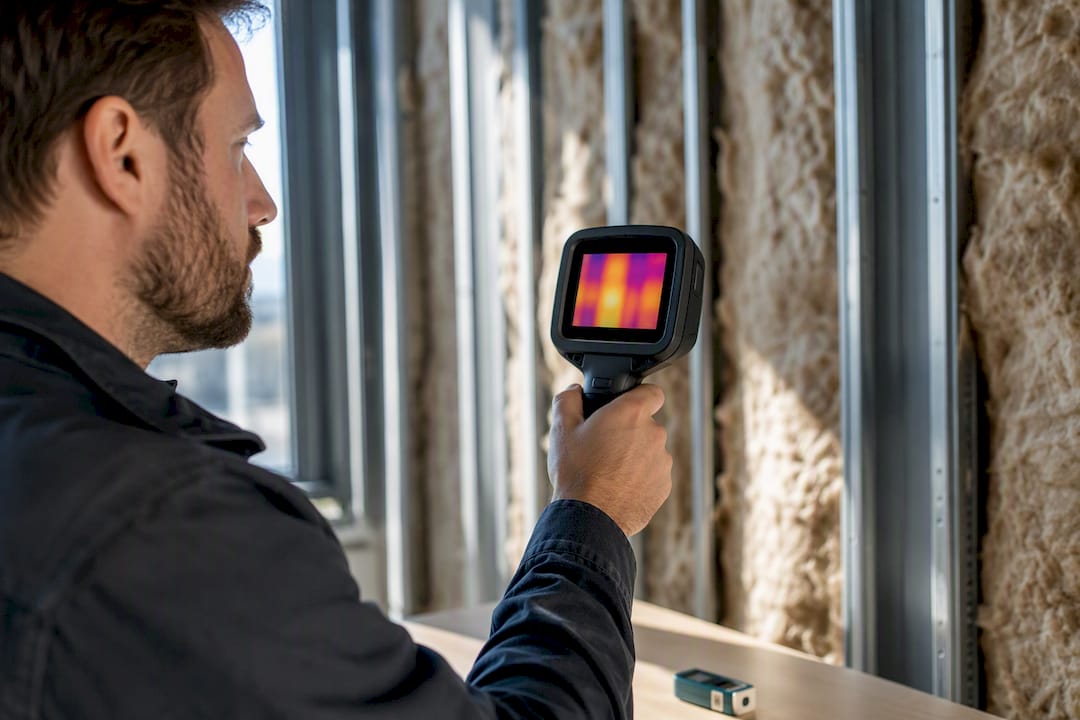
- Verify installed performance with thermal imaging or fRSI (frame surface temperature ratio) checks against dew-point calculations.
Pro Tip: Ask your energy modeler for the y-value, not just the nominal wall R-value. A wall can meet code on paper and still leak heat badly if the cumulative bridging isn’t accounted for.
Which Mitigation Strategies Actually Work?
Not every fix delivers the same return, and the research is specific about which ones do the heavy lifting.
Continuous exterior insulation is the single most effective move. Wrapping insulation, whether ETICS render systems or insulated panels, entirely outside the steel frame interrupts every stud and track bridge at once. Studies show exterior insulation can reduce the stud effect to values between about 0.4% and 1.4% in warm-frame configurations, which dwarfs what any single stud-level fix achieves.
Thermal break strips (TBS) placed between the stud flange and cladding help, but expectations should stay realistic. Thickness matters more than width: a thin strip delivered a modest thermal performance improvement, and a thicker strip yielded a somewhat larger improvement. TBS works best as a supplement, not a standalone solution.
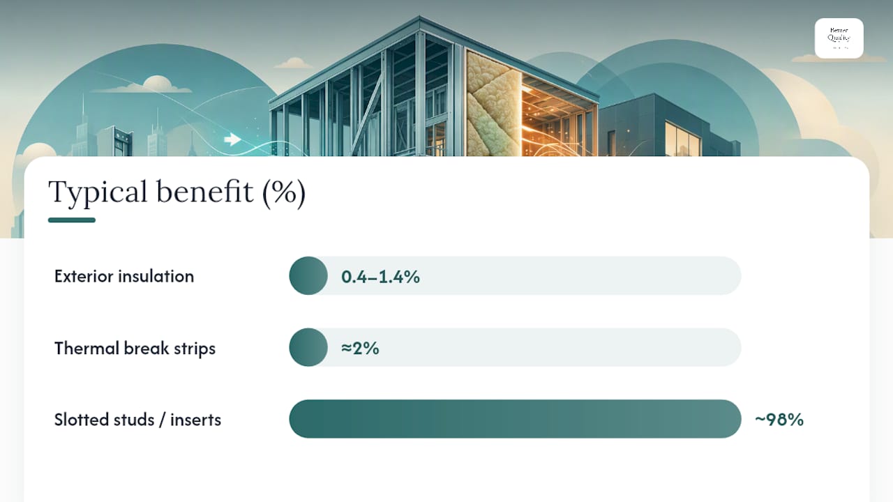
Slotted studs and web inserts made from less-conductive materials like polyamide punch above their weight. Some configurations cut modeled heat flux by as much as about 98%, though slotting reduces the steel’s structural capacity somewhat, so any change needs sign-off from a structural engineer.
Flange indentations as small as 2.5mm to 10mm can improve performance without exotic materials, but avoid filling them with low-performance fillers like recycled rubber, which studies have found counterproductive.
| Strategy | Typical benefit | Trade-off |
|---|---|---|
| Continuous exterior insulation | Stud effect reduced to under 1.5% | Adds wall thickness, detailing at openings |
| Thermal break strips (TBS) | about 2% per layer | Modest alone; needs correct thickness and uncompressed installation |
| Slotted studs / web inserts | Up to ~98% heat flux reduction | Reduces structural capacity; requires engineering review |
| Flange indentation | Measurable gain, low cost | Must avoid poor-performing fillers |
For structural penetrations like beams and balcony connections, engineered load-bearing thermal breaks are non-negotiable rather than optional, since these connections carry real structural loads and need to resist long-term creep. On site, the most common installation failure is compressing the TBS during fastening, which kills most of its benefit instantly. Learn more about how steel insulated panels handle continuous exterior insulation at the assembly level.
What Should You Put in Your Spec and Site Checklist?
Vague spec language is where good intentions go to die. Request specific numbers: a continuous exterior insulation R-target, TBS thickness and exact placement, and psi/chi values for any non-standard junction if the manufacturer or engineer can provide them.
On-site verification should include:
- Thermal imaging before cladding goes on, while cold spots are still visible and fixable.
- Confirmation that TBS material hasn’t been compressed by fastener over-torque.
- Fastener pattern review against the engineered detail, not just “close enough.”
- Sealed and insulated penetrations at every structural connection.
Any beam, column, or balcony connection carrying structural load needs an engineered thermal break, signed off by the structural engineer, not a field improvisation. Better Quality Builders has applied this discipline across projects built with AirLight steel panels, where continuous exterior insulation is built into the panel system itself rather than added as an afterthought.
Pro Tip: If a contractor can’t show you a thermal imaging report before drywall goes up, that’s your last easy chance to catch a bridging problem cheaply.
Why Integrated Thermal-Bridge Control Pays Off
Chasing thermal bridges after the walls are closed up is expensive and often impossible. Handling it at the design stage, with continuous exterior insulation and engineered breaks specified from day one, costs less than the callbacks for cold walls, condensation stains, or a utility bill nobody can explain. It also means fewer moisture claims years down the road, since corrosion at hidden steel connections doesn’t announce itself until the damage is already done.
The projects that get this right share one habit: the architect, structural engineer, and installer talk to each other before the steel goes up, not after someone notices a cold spot on the drywall.
— David Kobierski
Sources
- Thermal bridging in steel framed buildings — New Steel Construction tech paper
- CFSD report: Parametric analysis of steel stud thermal bridging (RP18-1)
- Thermal Breaks in Structural Steel — SEAC (2023)
- Parametric analysis of steel studs to reduce thermal bridges in light steel framing — MDPI (2025)